Developing a Temperature Control System
May 18, 2022 | Link to Github Repository
After several months of working on personal projects, I set myself the task of finding a project where I could work and learn as part of a team. That’s when I found a team of engineers developing an incubator for laboratories. After a quick call with one of the embedded engineers, I was assigned the task of helping in developing a temperature control system.
The goal of the project
The main goal of this project was to create a temperature control system to keep a constant temperature in an incubator. The project is based on an STM32 microcontroller and some of the main features include:
To date, all these features are ready and waiting for some real world testing once the custom PCB is finished. During the course of this project, I have learnt not only about embedded systems, but also about solving problems and team work.
Here are some of my main contributions, the main challenges I faced and the lessons I learnt.
From C to C++
When I first started this project, I was given the choice of using C or C++. I chose C because I had used it for all my previous projects and I had never had any problems with it. After a couple of months of working with C, the project started to get bigger than initially expected and the advantages of using an object-oriented programming language were becoming obvious. While I still like C because of its simplicity compared to C++, I have really enjoyed working with all the features C++ offers.
Reading ADC Channels
One of the first things I started working on was reading the data from the multiple ADC channels and converting it to voltage. To do this, I used a circular buffer and DMA. The main challenge of this part was finding a bug that wasn’t part of the code I had written, but from the STM32 auto-generated code.
STM32 has a very easy-to-use GUI to configure the hardware and it auto-generates the relevant code. For some reason, this code had a bug that prevented DMA from working properly when using it with ADC. This made me realise that I need to be careful when using GUIs that generate the code for me.
Setting up hardware and software timers
When we started the project we had a small microcontroller that didn’t have enough pins that supported hardware PWM, so we had to use a few GPIO to simulate PWM using interrupts. Apart from learning more about timers and PWM, the main lesson I got from writing this module was to always refer to the data sheet and reference manual when something is not working as expected. When checking the timers with a logic analyser, I noticed that the numbers in the code did not match what was being generated by the pin. That’s when I saw in the development board’s data sheet that the 8MHz crystal present was not being used for the main microcontroller, but for the debugging interface.
UART Communication
After writing the code to read ADC inputs and control the PWM pins, one important feature that we needed was a way to communicate with the microcontroller. This would be used to send messages from the MCU to a terminal and to send commands to the MCU for debugging.
In order to achieve this, I wrote the following modules:
FIFO Buffer
While C++ has std::queues to implement FIFO buffers easily, I wanted to write my own template class as a learning experience. One of the main problems I faced with this buffer was an error in the data received when I sent data via UART very quickly. This was caused by a race condition generated when an interrupt handler and the main program were accessing the buffer at the same time. To solve this, I opted to disable interrupts while the buffer was busy. While this could cause a delay in the data transfer, this was too small to make any difference.
JSON-based parser
This is another feature that could have been easily added by using third-party libraries. However, my goal was to learn as much as I could, so I wrote my own JSON-based parser to process incoming commands. To achieve this, I divided the parser into two parts: a tokeniser and the actual parser.
The job of the tokeniser is to process the strings coming from the communications channel, in order to obtain tokens and then store the tokens in a buffer. A token, in this case, is the basic building block of a JSON string. These are: curly braces, square brackets, colon, commas, strings and numbers.
With all the tokens in the buffer, the parser processes them using recursive functions to identify if the string is a JSON string and if it has the right components.
Writing this parser was more challenging than I expected, and it helped me understand better how to use state machines and recursive functions.
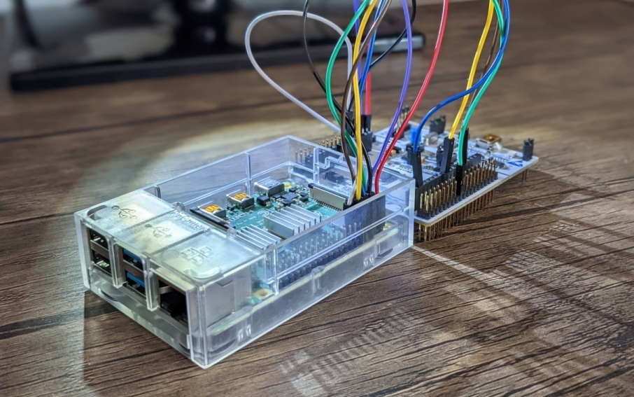
Setting up HIL Testing
With most of the code in a working state, I decided to learn a bit more about DevOps and set up Hardware in the loop testing using a Raspberry Pi and a Nucleo-64 board. One of the engineers in the team had already set up a Github Action to check the application would build successfully using docker. This process generates a binary file that was very useful for setting up HIL.
The first step was to flash the STM32 using the Raspberry Pi. To do this, I wrote a Python script that used the pre-loaded bootloader in the STM32 to download the code using UART.
Once I checked this script worked correctly, it was time to connect the Raspberry Pi to Github. The first part was to set up the Raspberry Pi as a self-hosted runner, which meant Github could use it to run jobs every time a merge request was created. The next step was to define the workflow to do the following:
Doing this was a very interesting and challenging experience, and I am now in the process of writing the tests for the STM32.
Working with this team has been an invaluable experience. Sharing ideas, giving and receiving feedback and discussing things in a constructive way has helped me become a better embedded engineer and I can’t wait to see what the future holds.
Thanks for reading!